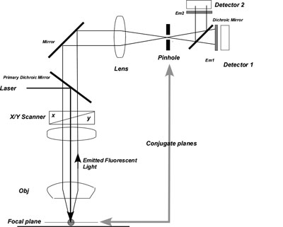
Confocal microscopy acquires sample image light from the focal plane of the microscope objective and rejects all other sample light that arises from out-of-focus positions. Rejection is accomplished by placing a pinhole in an optical plane conjugate, or confocal, to the sample plane but in front of the light detector. Here, light from other positions within the sample is blocked or is greatly attenuated by the pinhole stop. Light emanating from the sample plane passes through the pinhole, is recorded and eventually transformed into an image. The pinhole diameter range of 50–200 µm eliminates as much out-of-focus light as possible while passing a detectable amount of focal plane light. The small diameter of the pinhole is designed to match the diameter of the Airy disc to increase resolution and decrease the thickness of the optical plane (confocal slice thickness). Maximum resolution is achieved when the pinhole diameter is the same size or slightly smaller than the Airy disc; which eliminates the associated diffraction rings and resolution-limiting wave interference. All modern (post 2008) confocal microscopes have a single pinhole for all detectors. However, when scanned on a line-basis (Zeiss "MultiTracking") this results in slightly different confocal slice thicknesses between excitation wavelengths. When the pinhole is set to approximately 1 Airy, confocal slice thickness is a function of pinhole diameter and Emission wavelength. The mismatch in confocal slice thickness, as a result of a "source" single pinhole is particularly apparent when imaging a sample at widely differing Em wavelengths. e.g., DAPI vs Cy3. Slice thickness mismatch can be avoided if the pinhole diameter is normalized for each Ex wavelength during Z-scanning.
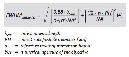 This equation from Carl Zeiss Inc describes the parameters of the confocal slice thickness.
In order to create an image, light from every point in the sample plane must be projected through the pinhole and recorded. There are two methods used to form an image. One method scans the sample at a rapid rate (using either multiple pinholes or an illumination slit) and projects the light onto an image plane in near real-time. Video rate microscopes often detect sample light with an area detector such as a CCD digital camera, or the human eye, thus allowing true color images to be seen. However, rapid scanning decreases the total amount of acquired light, and thus the level of the signal that may be detected.
An alternate method scans the entire sample at a much slower rate with only one illumination spot. Light from each sample plane position is stored in a computer image file as a single intensity value, along with the x, y, and z (focus position) coordinates. To acquire an array of point, or pixel, values, the microscope scans the object in a regular pattern (“raster” or saw tooth) with excitation (laser) light, and samples the emitted light at periodic intervals (usually milliseconds per pixel). Each imaged sample point is painted to a computer screen at the appropriate coordinates, intensity values, and channel colors to reconstruct the confocal sample slice. Computer image processing is used subsequently to reconstruct each image, thus observation of the sample is not in real-time but can take 3–20s per optical section (depending on scan resolution, number of channels, etc).The detectors are usually PhotoMultiplier Tubes.
3-dimensional images are created by imaging successive focal planes.
There are two dichrioc mirrors shown. The Primary Dichroic Mirror reflects lower wavelength laser light onto the sample. The upper Mirror (past the pinhole) serves to transmit emitted light from the sample laterally to the detectors for multiple channel imaging.